


5. Establishing Good Reception
The most important aspect of a radio system is its ability to provide a high quality stable link without pops, crackles, distortion, or background noise. This is technically hard to achieve as there are many external influences which can upset the smooth operation of a set-up:
- Poor line-of-sight, i.e. the signal path from antenna to antenna is interrupted by one or more obstacles. This is more problematic at high carrier frequencies because the higher the frequency, the less the radio wave is able to diffract around objects.
- Reflections - radio waves bounce off objects in the same way as light. This can lead to the receiver picking up the signal at two or more very slightly different points in time, due to the path differences of the reflections. As radio waves travel at the speed of light there will be no audible delay or echo, but there can be a phase conflict at the receiver giving rise to constructive and/or destructive interference. This can manifest itself as dead spots at certain positions on the stage.
- Range - there is a limit to the distance that can be placed between the transmitter and the receiver - go over this limit and the signal will cut out. However, unless using in-ear monitoring, perceived audio delay due to the speed of sound in air is likely to be more of a problem for the player, due to his distance from the monitors!
- Batteries - the power and therefore the range of transmission is governed by the charge in the battery. Good onboard metering of battery life is essential for risk-free performance. Most units have an LED or LCD display for low-battery warnings. In order to maintain a constant power output as the battery drains, internal voltage regulators are used. The disadvantage of this is that when the battery is nearly used up, the unit can stop functioning very quickly after the warning. For this reason, its important to change batteries before every gig, even if there appears to be plenty of life left in the previous ones. Rechargeables might seem like a good idea, but these typically offer much less life per charge than regular dry-cell batteries you pays your money and takes your choice!
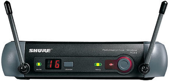
In order to minimise transfer errors effectively, most manufacturers use so-called diversity receivers. A little background information is required to understand this principle; when transmitting and receiving antennas have the same orientation, i.e. both vertical or both horizontal - or both anything in between as long as its the same - then the received radio signal is at a maximum. On the other hand, when the antennas are effectively at right angles to one another, signal strength is at a minimum and this is when transfer errors are most likely. The typical guitarist however is moving all over the stage, taking his transmitter antenna with him, and is unlikely to show much interest in maximising its orientation at the peak of his shred-tastic solo. To get around the problem, diversity receivers actually consist of two separate receivers both listening to the same channel via two separate antennas placed at right angles to each other in a V configuration. This positioning ensures that one antenna is always supplied with a sufficiently strong signal, regardless of the orientation of the transmitters antenna. Built-in electronics constantly measure the signal strengths of each antenna, and automatically noiselessly switch to the dominant receiver. There is usually an LED display to show which receiver is active.
If there are still some signal disturbances, or a gap in playing, a further important standard feature intervenes - muting or squelch as it is otherwise known. When a receiver detects a very weak signal (short term), it subtly switches itself off momentarily, effectively suppressing the extremely unpleasant noise which would otherwise occur under these conditions. The squelch threshold level can is often user controllable.
A further technology called pilot reference gives a third line of defence against receive errors. Here, the transmitter adds a coded signal to the audio information which controls muting at the receiver. Each transmitter channel has its own unique code which is known to the receiver, and if this code is not detected at the receiver end then the receiver will not open the channel. This method of interference rejection is primarily effective against problems caused by local radio traffic on the same carrier frequency the classic minicab announcer coming through your stack scenario!
Your Contacts
Product Highlights


Offers
-
Wireless Systems for Guitar and Bass
-
Guitar and Bass Wireless